Traffic diagnostic controllers of TDC series (hereinafter TDC) of SEA Company production are intended for:
TDC can be used in different environment and climatic zones with temperature range from – 40° C to + 70° C and in a range of power voltage from 160 V to 250 V.
The principal goals to be achieved during design and development of TDC were: maximum fail-safety security, functional reliability, convenient operation in different working conditions. The multi-level control system completely excludes the possibility of occurrence the critical conditions of traffic-light object.
The last 10 years of microprocessor and computer equipment development shows a firm tendency for using standardized interfaces and PC-compatible architecture of computer systems building.
Taking into consideration these tendencies, it was decided to choose industrial PC – compatible computer as functional core of TDC. It allows:
Use worldwide produced standardized equipment (main-boards, modems, Flesh-memory, video-monitors, mobile computers, printers, etc.) as additional equipment compatible with TDC.
Usage of PC – compatible computer as a functional core of the traffic controller, will considerably save financial expenses in future.
Traffic controller TDC is produced on a basis of a module mode.
|
Item description |
Number of blocks in TDC models |
|||
|
TDC - 8 |
TDC - 16 |
TDC - 24 |
TDC - 32 |
|
|
Layout box |
1 |
1 |
1 |
1 |
|
Power contact block |
1 |
1 |
2 |
2 |
|
Electric meter |
1 |
1 |
1 |
1 |
|
Switching unit |
1 |
1 |
1 |
1 |
|
Double-pole circuit breaker |
1 |
1 |
1 |
1 |
|
Heating element (HE) |
1 |
1 |
1 |
1 |
|
Computer module (CM) |
1 |
1 |
1 |
1 |
|
Power supply unit (PSU) |
1 |
1 |
1 |
1 |
|
Block of power channels (BPC) |
1 |
2 |
3 |
4 |
|
Interface |
Optional at customer’s will |
|||
|
Accumulator module (AM) |
Optional at customer’s will |
|||
|
Engineering station |
Optional at customer’s will |
|||
Traffic controllers TDC -40, TDC -48, TDC -56, TDC -64 with power channels 40, 48, 56, 64 accordingly, can also be produced at customer’s request.
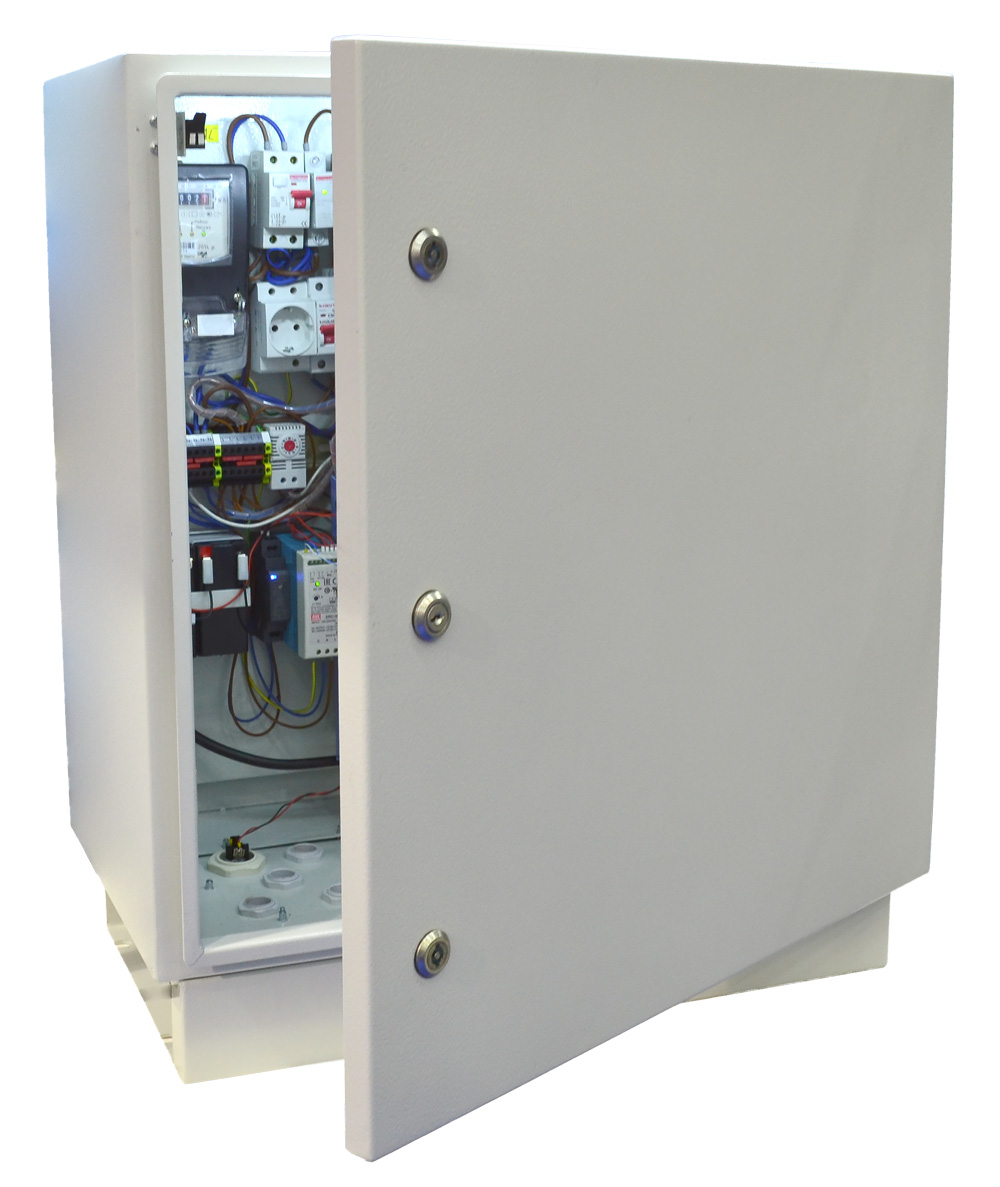
Layout box, TDC blocks/modules (PSU, BPC, CM, AM) are produced in powder painted metal bodies. Front panels contain plugs and LEDs which inform about TDC operating mode. Plugs are chosen on the basis of their functionality and maximum reliability of the contacts, and number of LED’s is specified by maximum informational content.
On the front panel of processor module situated connector for connection to external display, which helps to implement additional control of traffic controller functioning state and traffic light objects, installed at it. At the bottom of layout box situated connector for engineering desk, which helps to implement full diagnostics of functioning state of controller and row of LED lamps and attune of traffic light objects, installed at controller.
TDC has three-wire power supply diagram (phase, zero, safety ground)
TDC has 1st grade of accuracy counter of electric power consumption and bipolar breaker assembly.
Adjusting bracket allows to place traffic controller on electro-support or building wall.
Layout box of controller has anti-vandal protection: 2 special screws, mortise lock. Unapproved open of door will be registered by build in door sensor and recorded at the city control centre through communication channel.
Option “contact lock” can be useful. At the bottom of layout box can be placed lock with build in contact group. Using of this option allows to switch traffic light object to mode of yellow blinking and backwards without open of the box.
BPC can be supplied in two variants: for management of lamp- and LED traffic lights. BPC for lamp traffic lights has “smooth start” mode, which increases life cycle of traffic light lamps.
All power lines have 4-level protection system from overwork and short circuits:
With appearance of apparatus defects in the load circuits (overworks which exceed preset threshold, closing of load circuit, unapproved shining of green lamps), controller switches off these circuits for allowed time. After prescribed time controller verifies occurrence of defects at earlier switched off circuits and in case of normalization of situation switches on verified circuits.
There is a possibility of realization of program regime “black box”, which allows to get information about TDC equipment state and operating modes of installed at it traffic light objects. This helps to find out state of traffic light signalization at cross-road in case of road traffic accident. Data of “black box” will be useful for examination of defects history of TDC, load circuits and installed at controller traffic light objects.
Engineering station – it is a program production unit performed on the basis of mobile PC – compatible with computer.
It can be installed workbench “Engineer” to the engineering station, which is designed for operating with TDC equipment and load circuit of light-signal lamps and workbench “Technologist”, which is designed for operating with work scripts of light-signal objects, with workmanship instructions of light-signal objects.
To perform manually the diagnostic of power channels in different ways (“all red” + “yellow blinking”, “all green” + “yellow blinking”, “specific channel” + “yellow blinking”).
|
Parameter |
Meaning |
||
|
The quantity of power channels |
From 8 up to 64 |
||
|
Power supply voltage |
From 160V up to 250V |
||
|
Controlled channel load |
in BPC for LED matrix |
From 2 W up to 100 W |
|
|
in BPC for incandescent lamps |
From 40 W up to 600 W |
||
|
General load current |
Is defined by automatic overload control, by counter, by section of lead wire and by customer needs |
||
|
Operating temperature range |
From -40ºC up to +70ºC |
||
|
Countdown accuracy |
Is defined by the type of selected PC and operating system, but not more than 1 minute per month |
||
|
Real time clock battery life |
Up to 5 years |
||
|
Control modes |
Hardware-controlled, by the switch of power supply or “lead lock” option |
||
|
Manual control from the engineering station |
|||
|
Annual calendar automation, according to internal instructions of RDC |
|||
|
Coordinated control in accordance with instructions, received through the communication channels |
|||
|
Direct dispatcher control from the control center |
|||
|
The quantity of possible work scripts |
16 |
||
|
The quantity of possible work instructions |
Unlimited |
||
|
Capacity of no-break power battery, A/hour |
7 |
||
|
Time of system working capacity from battery without switching to “sleep mode”, hours |
7 |
RDC contacts the city control center at the appointed time and informs about the lack of power supply. Then TC occasionally switches off the “sleep mode” and control the availability of mains supply. |
|
|
Time of system working capacity from battery with switching to “sleep mode”, hours |
48 |
||
|
Interface type of internal information network |
RS-232 multiplexer |
||
|
Types of external communications protocol of TC (city system of road traffic control, etc.) |
Protocol types of information interaction of TC road controllers in the city road traffic control system are defined by the executor of this system and will be supported by the road controller. GPRS, TCP/IP protocols are implemented at the moment |
||
|
Possible types of connection channels |
Road controllers TC can interact with city control center through any communication channel. The main communication channel – GPRS and emergency communication channel – voice channel GSM are enabled in the block now. |
||
|
Dimensions, mm, not more |
850x450x350 |
||
|
The weight of controller |
Is defined by the kitting-up, but not more than 50 kgs |
||
|
Level distance between fixing points, mm |
370 |
||
In order to buy traffic controller or get more information, please contact our main office on +38 (044) 330-00-88 or e-mail: info@sea.com.ua
